


Wedge Gate Valve: Types, Working Principle, Design, Applications & Selection Guide
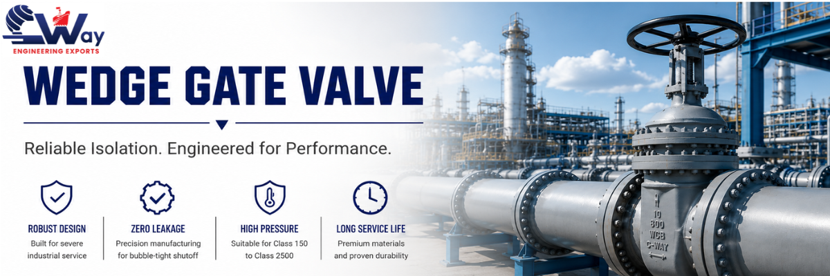
A wedge gate valve is one of the most widely used industrial isolation valves for controlling the flow of liquids, gases, steam, and other process media in pipelines. Unlike control valves, a wedge gate valve is designed to operate in either the fully open or fully closed position, providing minimal pressure loss during operation and reliable shut-off when closed.
The wedge-shaped gate moves linearly between two inclined seating surfaces, converting axial stem thrust into sealing force. This design provides tight shut-off performance while maintaining a straight-through flow path when the valve is fully open.
Wedge gate valves are widely used in oil & gas, petrochemical, refinery, power generation, water treatment, marine, mining, and chemical processing industries where dependable isolation is essential.
This comprehensive engineering guide explains the wedge gate valve working principle, internal construction, wedge designs, materials, trim selection, pressure classes, industrial applications, testing standards, inspection requirements, maintenance practices, troubleshooting, and valve selection criteria to help engineers, EPC contractors, procurement teams, and plant operators choose the right valve for their application.
What Is a Wedge Gate Valve?
A wedge gate valve is an isolation valve that uses a tapered gate moving between two inclined seating surfaces. During closing, the stem drives the wedge into the seat region. During opening, the wedge is lifted completely out of the main flow path.
The wedge and body seats are manufactured with corresponding angular geometry. As the closure element approaches the fully closed position, contact develops between the two wedge seating faces and the corresponding body seats.
The principal design objectives are:
- low flow restriction when fully open
- reliable isolation when fully closed
- controlled guidance of the wedge during travel
- sufficient stem thrust for opening and closing
- stable seat contact under specified pressure and temperature conditions
- acceptable operating torque throughout the valve life
A wedge gate valve is fundamentally an on-off valve. It should not normally be selected for continuous throttling because partial opening exposes the wedge and seats to concentrated high-velocity flow, turbulence, vibration, wire drawing, and localized erosion.
When Should You Use a Wedge Gate Valve?
Use a wedge gate valve when the application requires complete flow isolation with minimal pressure loss during operation. These valves are particularly suitable for pipelines that normally remain either fully open or fully closed and are not intended for continuous throttling service.
Typical applications include:
- Oil & Gas pipelines
- Petrochemical plants
- Refineries
- Steam distribution systems
- Water treatment facilities
- Power generation plants
- Chemical processing industries
- Marine piping systems
Wedge gate valves are preferred where low flow resistance, bi-directional sealing capability, and reliable long-term shut-off performance are important design requirements.
Wedge Gate Valve Working Principle: How Does It Work?
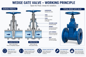
A wedge gate valve works by converting handwheel or actuator input into linear stem movement that raises or lowers the wedge between two inclined seats. In the fully open position, the wedge clears the bore. In the closed position, the wedge engages both seating surfaces to isolate flow.
The operating sequence involves three interacting systems:
- Operating mechanism – handwheel, gearbox, or actuator provides torque.
- Stem system – converts or transmits operating input into axial movement and thrust.
- Closure system – wedge, guides, and seats control travel and final shutoff.
Understanding these three systems is important because a valve can experience high torque even when the seating surfaces themselves are undamaged. Stem friction, packing compression, guide interference, thermal distortion, deposits, and differential pressure can all contribute to operating load.
Opening Cycle
When the valve is opened, the stem mechanism lifts the wedge away from the body seats.
The sequence is approximately:
- operating torque is applied
- the stem develops axial lifting force
- the wedge begins to unload from the seats
- seating contact reduces
- the wedge travels upward through the body guides
- the flow area progressively increases
- the wedge clears the main bore in the fully open position
The initial movement can require significant force because the operator must overcome a combination of:
- seating friction
- packing friction
- stem thread friction
- differential-pressure effects
- guide friction
- deposits or corrosion
- thermal binding where present
For actuated valves, this is one reason actuator sizing should not be based only on nominal valve size.
Closing Cycle
During closing, the stem drives the wedge toward the seat region.
The sequence is:
- the wedge moves downward through the guides
- the available flow area decreases
- fluid velocity through the remaining opening increases
- the wedge enters the seating region
- contact develops between wedge faces and body seats
- final stem thrust establishes the designed closed position
Near closure, flow conditions can become severe because a large pressure differential may be concentrated across a relatively small opening. Repeated slow operation near the seat region can contribute to erosion and seating damage.
How Wedge Geometry Produces Seating Contact
The closure element is not simply a flat plate. Its two seating faces are inclined relative to each other and correspond with the body seat geometry.
When axial stem force acts on the wedge, the inclined geometry creates contact forces at the two seating interfaces.
In simplified form:
Axial stem thrust → wedge movement → seat contact → sealing interface
However, actual sealing behavior is influenced by:
- wedge angle
- coefficient of friction
- seat surface finish
- seating band width
- differential pressure
- material hardness
- body deformation
- thermal expansion
- guide clearance
- manufacturing alignment
Excessive interference can increase operating torque and promote binding. Insufficient or uneven contact can contribute to seat leakage.
For this reason, wedge and seat geometry must be controlled as a matched functional system.
Wedge Gate Valve Parts and Construction
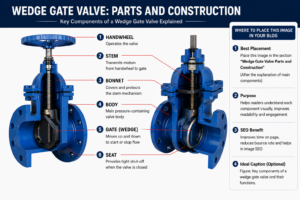
A wedge gate valve is a pressure-containing mechanical assembly in which the body, bonnet, wedge, seats, stem, guides, packing system, and operating mechanism must function together.
Valve Body
The body contains the flow passage, supports the seat region, guides the closure element, and forms the primary pressure boundary.
From a manufacturing perspective, critical body features include:
- end connection geometry
- seat pocket alignment
- guide alignment
- body-bonnet joint
- wall thickness
- flange alignment
- machining datum control
- internal flow passage
Body distortion can directly affect valve operation. If the relationship between the two seats changes because of casting distortion, welding stress, piping loads, or thermal gradients, wedge contact may become uneven.
This can lead to:
- increased operating torque
- incomplete seating
- localized seat loading
- wedge jamming
- leakage
Common body materials include:
- ASTM A216 WCB carbon steel
- ASTM A351 CF8
- ASTM A351 CF8M
- ASTM A351 CF3
- ASTM A351 CF3M
- alloy steel castings
- duplex stainless steel
- ductile iron
- cast iron
- nickel-alloy materials
Material selection should follow pressure-temperature requirements and corrosion assessment.
Bonnet Design
The bonnet closes the upper pressure boundary and supports the stem sealing system.
Common constructions include:
Bolted Bonnet
A bolted bonnet uses a mechanical body-bonnet joint with gasket sealing and bolting.
It is widely used because it provides:
- access to internal components
- established manufacturing practice
- serviceability
- broad size and pressure-class coverage
Engineering considerations include:
- gasket type
- flange rigidity
- bolt loading
- surface finish
- thermal cycling
- assembly procedure
Welded Bonnet
A welded bonnet eliminates the conventional bolted body-bonnet gasketed joint.
It may be used where:
- compact construction is required
- external leak paths must be minimized
- maintenance philosophy permits welded construction
Repair and internal access requirements should be considered before selection.
Pressure Seal Bonnet
Pressure seal construction is associated with high-pressure and high-temperature applications.
Unlike a conventional bolted bonnet joint, internal pressure contributes to loading the pressure seal gasket against its sealing surfaces.
Typical applications may include:
- high-pressure steam
- power generation
- boiler systems
- severe high-temperature process service
Pressure seal performance depends strongly on:
- gasket material
- contact surface condition
- dimensional accuracy
- assembly procedure
- pressure and temperature cycling
Wedge or Gate Disc
The wedge is the primary closure component.
Critical manufacturing and design features include:
- seating face angle
- seating surface finish
- wedge thickness
- guide geometry
- stem connection
- material
- hardfacing
- dimensional symmetry
Poor wedge geometry can produce uneven seat loading even when the body seats are correctly machined.
Seat Rings and Seating Surfaces
The seats establish the shutoff interface with the wedge.
Depending on valve construction, seats may be:
- integral with the body
- renewable threaded seat rings
- welded-in seat rings
- hardfaced seating surfaces
Critical seat characteristics include:
- concentricity
- angular alignment
- surface finish
- contact band
- hardness
- corrosion resistance
- erosion resistance
- galling resistance
Stem Design and Stem Loading
The stem transmits operating force between the handwheel or actuator and the wedge.
Critical stem design factors include:
- stem diameter
- thread form
- thread engagement
- material strength
- surface finish
- straightness
- corrosion resistance
- connection to the wedge
Packing and Gland System
The packing system controls external leakage around the moving stem.
Performance depends on:
- packing material
- packing ring geometry
- stem finish
- gland loading
- temperature
- pressure
- process fluid
- operating frequency
Excessive gland compression may reduce leakage initially but can sharply increase stem friction and operating torque.
Insufficient compression can result in external leakage.
Where fugitive-emission performance is required, the complete stem sealing system should be evaluated, including:
- packing material
- stem surface finish
- gland design
- live loading where specified
- thermal cycling
- mechanical cycling
Body and Wedge Guides
Guides control lateral movement of the wedge during opening and closing.
Common Body Materials
| Material | Typical Service |
|---|---|
| ASTM A216 WCB | General Industrial Service |
| ASTM A351 CF8 | Water & Utilities |
| ASTM A351 CF8M | Chemical Processing |
| Duplex Stainless Steel | Offshore Pipelines |
| Super Duplex | Seawater Service |
| Alloy Steel | High Temperature Applications |
Guide design is important because excessive clearance can allow:
- wedge movement
- vibration
- uneven seat approach
- impact
Insufficient clearance can create:
- high friction
- jamming
- sensitivity to thermal expansion
- seizure caused by deposits
Guide clearance therefore requires balance between stable wedge movement and sufficient operating freedom.
Wedge Gate Valve vs Parallel Slide Gate Valve
| Feature | Wedge Gate Valve | Parallel Slide Gate Valve |
|---|---|---|
| Closing Element | Wedge | Parallel discs |
| Isolation | Excellent | Excellent |
| Thermal Expansion | May require flexible wedge | Better for high-temperature steam |
| Typical Industry | Oil & Gas | Power Plants |
| Seat Contact | Wedge action | Parallel seating |
| Flow Restriction | Very Low | Very Low |
Types of Wedge Gate Valves: Solid, Flexible and Split Wedge
The three main types of wedge gate valves are solid wedge, flexible wedge, and split wedge. Their primary engineering difference is the way the closure element responds to seat alignment, thermal expansion, body distortion, and mechanical loading.
Solid Wedge Gate Valve
A solid wedge gate valve uses a one-piece rigid closure element.
Its primary advantages are mechanical simplicity and structural robustness.
Design Characteristics
- one-piece wedge
- high structural rigidity
- simple load path
- limited elastic accommodation
- broad material availability
Engineering Advantages
Solid wedge designs offer:
- simple manufacturing concept
- robust construction
- fewer internal closure components
- suitability for many general isolation services
Engineering Limitations
The same rigidity that provides mechanical simplicity also reduces the ability to accommodate changes in seat relationship.
Potential problems include:
- thermal binding
- sensitivity to body distortion
- high unseating force
- uneven contact if seat alignment changes
A solid wedge is therefore not automatically the best choice for every temperature-variable service.
Flexible Wedge Gate Valve
A flexible wedge gate valve generally uses a one-piece closure element with a machined reduced section that allows limited elastic deflection between the two seating portions.
This is a significant engineering distinction.
The flexible section allows the two seating faces to accommodate small changes in relative position while retaining a one-piece closure element.
How a Flexible Wedge Works
When seating loads develop, the reduced-section geometry permits controlled elastic deformation.
This can help accommodate:
- small seat misalignment
- body distortion
- differential thermal expansion
- dimensional changes during operation
The amount of flexibility is not arbitrary. It depends on:
- groove geometry
- remaining section thickness
- wedge diameter
- material modulus
- applied load
- pressure
- temperature
If the section is too rigid, the intended accommodation is reduced.
If it is excessively flexible, cyclic stress and structural performance become concerns.
Typical Service Considerations
Flexible wedge designs are often evaluated for:
- steam service
- power generation
- refineries
- petrochemical plants
- elevated-temperature systems
- temperature-variable process conditions
Selection should still be based on the complete valve design.
Split Wedge Gate Valve
A split wedge gate valve uses separate closure components rather than one rigid wedge.
The individual components can accommodate the seat relationship differently from a solid one-piece design.
Engineering Characteristics
Potential characteristics include:
- multi-piece closure construction
- independent or semi-independent seating behavior
- greater accommodation of certain seat relationships
- increased internal mechanical complexity
Selection Considerations
The design should be evaluated for:
- process cleanliness
- deposits
- wear
- internal component movement
- maintenance
- orientation
- service conditions
A split wedge should not be selected only because it appears more flexible. The complete internal mechanism must suit the process medium.
Solid Wedge vs Flexible Wedge vs Split Wedge
| Engineering Factor | Solid Wedge | Flexible Wedge | Split Wedge |
| Construction | One-piece rigid | One-piece flexible section | Multi-piece |
| Structural rigidity | High | Moderate | Design dependent |
| Seat accommodation | Limited | Controlled elastic accommodation | Greater in some designs |
| Thermal distortion tolerance | Lower | Generally improved | Design dependent |
| Internal complexity | Low | Moderate | Higher |
| Deposit sensitivity | Lower | Service dependent | Potentially higher |
| Typical selection basis | General isolation | Temperature-variable or demanding service | Specific seating requirements |
| Key concern | Binding | Flexible-section stress | Component interaction |
Rising Stem vs Non-Rising Stem Wedge Gate Valves
Rising Stem Gate Valve
In a rising stem design, rotational input causes the stem to move axially upward or downward.
The external stem position provides direct visual indication of valve travel.
Advantages include:
- visible position indication
- easier assessment of open or closed status
- stem threads isolated from process fluid in many designs
Engineering considerations include:
- vertical clearance
- stem protection
- environmental corrosion
- yoke alignment
Non-Rising Stem Gate Valve
In a non-rising stem design, the external stem position remains substantially fixed while threaded interaction produces movement of the gate.
Advantages include:
- reduced installation height
- suitability for confined spaces
- compact external envelope
Considerations include:
- process exposure of threaded components in some designs
- lubrication
- corrosion
- less direct visual position indication
Wedge Gate Valve Trim Materials and Hardfacing
The term trim refers to internal components associated with closure, seating, and stem operation. Exact trim definitions can vary with the governing specification.
Critical trim components may include:
- stem
- wedge seating surfaces
- body seats
- seat rings
- backseat components
Trim selection affects:
- corrosion resistance
- erosion resistance
- galling resistance
- temperature capability
- wear
- operating torque
Why Seat Hardness Matters
When two metallic surfaces move under load, poor material pairing can increase the risk of:
- galling
- adhesive wear
- scoring
- seizure
For this reason, seat and wedge surface combinations should be selected with consideration of hardness differential and compatibility.
Hardfacing
Hardfacing may be applied where improved resistance is required against:
- wear
- erosion
- galling
- high-temperature degradation
The correct hardfacing system depends on:
- process fluid
- temperature
- corrosion conditions
- specification
- manufacturing process
Hardfacing should not be treated as universally beneficial. Material compatibility and cracking risk must also be considered.
End Connections
Flanged End Gate Valve
Flanged connections allow bolted connection to the piping system.
The specification should define:
- nominal size
- pressure class
- flange standard
- facing
- material
Butt Weld Gate Valve
Butt weld ends are frequently selected for:
- high-pressure systems
- high-temperature service
- critical process piping
- reduced flange leak paths
Engineering considerations include:
- weld-end preparation
- material compatibility
- welding procedure
- preheat
- post-weld heat treatment where required
- protection of valve internals during welding
Socket Weld and Threaded Gate Valves
Smaller forged steel gate valves may use:
- socket weld ends
- NPT threaded ends
These configurations are common in small-bore process piping where permitted by the piping specification.
Wedge Gate Valve Applications by Industry
Wedge gate valves are widely used for isolation in oil and gas, refineries, petrochemical plants, power generation, water and wastewater, and chemical processing. These applications require suitable pressure class, hydrocarbon compatibility, fire-safe design, and fugitive-emission control, while refinery and petrochemical service must consider temperature cycling, corrosion, steam, and process conditions.
Typical Pressure Classes
| Pressure Class | Typical Applications |
|---|---|
| ANSI 150 | Water distribution, HVAC |
| ANSI 300 | Oil & Gas pipelines |
| ANSI 600 | Petrochemical & Refineries |
| ANSI 900 | Steam service |
| ANSI 1500 | High-pressure process plants |
| ANSI 2500 | Severe service applications |
How to Select a Wedge Gate Valve
Select a wedge gate valve based on the process medium, chemical composition, design pressure, differential pressure, operating temperature, and thermal cycling conditions. Choose a solid, flexible, or split wedge according to service severity and seat accommodation requirements, then specify compatible body and trim materials, pressure class, and flanged, butt weld, socket weld, or threaded ends. Confirm the required rising or non-rising stem design, manual or actuated operation, applicable valve standards, testing criteria, inspection requirements, and documentation before manufacturing.
Wedge Gate Valve Torque and Actuator Sizing
Actuator sizing should be based on validated valve operating loads rather than nominal size alone. Required torque or stem thrust is influenced by differential pressure, wedge geometry, seat and packing friction, stem-thread friction, guide resistance, temperature, deposits, and valve orientation. Selection should consider break-to-open, running, seating, and unseating loads with an appropriate design margin, while avoiding excessive actuator output that could damage the stem, wedge, seats, or gearbox.
Wedge Gate Valve Testing and Inspection
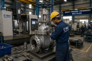
Testing should verify pressure-boundary integrity and closure performance according to the applicable specification.
Commonly referenced standards include:
- API 598
- ISO 5208
- EN 12266-1
Shell Test
The shell test evaluates the pressure-containing boundary.
Areas under evaluation include:
- body
- bonnet
- body-bonnet joint
- pressure-containing connections
The test pressure, duration, medium, and acceptance criteria depend on the applicable standard.
Seat Leakage Test
The seat test evaluates closure performance.
Important variables include:
- test direction
- test pressure
- test medium
- duration
- allowable leakage rate
- valve design
A statement such as “zero leakage” should not be used casually. Acceptance must be defined against the specified test standard and leakage criterion.
Additional Inspection
Depending on project requirements:
- PMI
- radiography
- ultrasonic examination
- magnetic particle examination
- liquid penetrant examination
- dimensional inspection
- hardness testing
- material traceability may be required.
Wedge Gate Valve Standards
| Standard | Technical Relevance |
| API 600 | Steel gate valves within covered scope |
| API 602 | Compact steel gate valves within covered scope |
| ASME B16.34 | Pressure-temperature ratings and valve requirements within scope |
| API 598 | Inspection and testing |
| ISO 5208 | Pressure testing of metallic valves |
| EN 12266-1 | Industrial valve pressure testing |
| ASME B16.10 | Face-to-face and end-to-end dimensions |
| ASME B16.5 | Flange dimensions and ratings within scope |
| ASME B16.25 | Butt-welding ends |
Standards should be specified according to their actual scope. Combining unrelated requirements without confirming compatibility can create procurement and manufacturing conflicts.
Wedge Gate Valve Selection Checklist
A wedge gate valve should be selected as a complete mechanical and pressure-containing system—not simply by nominal size and pressure class.
Reliable operation depends on the interaction of:
- wedge geometry
- seat alignment
- stem thrust
- guide clearance
- body rigidity
- trim materials
- packing friction
- differential pressure
- thermal expansion
- actuator output
- manufacturing tolerances
- installation loads
For general isolation duties, a solid wedge may provide a robust and mechanically simple solution. For temperature-variable service, a flexible wedge may offer improved accommodation of small dimensional changes. Split wedge designs may be appropriate where their particular seating behavior suits the application.
A technically complete valve specification should define the process medium, design pressure and temperature, differential pressure, material requirements, wedge type, pressure class, end connections, operation method, testing standard, leakage acceptance criteria, inspection requirements, and documentation before manufacturing begins.
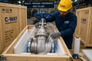
C-Way Engineering Exports manufactures and exports industrial wedge gate valves designed for demanding applications across oil & gas, petrochemical, power generation, water treatment, marine, and industrial processing sectors.
Our manufacturing capabilities include:
- Carbon Steel Wedge Gate Valves
- Stainless Steel Wedge Gate Valves
- Duplex & Super Duplex Gate Valves
- Alloy Steel Gate Valves
- API 600 Gate Valves
- API 602 Forged Steel Gate Valves
- ANSI Class 150 to 2500
- Flanged, Butt Weld, Socket Weld, and Threaded Ends
- Manual, Gear Operated, Electric & Pneumatic Actuated Valves
Contact our engineering team for product selection, technical datasheets, pressure rating information, and project-specific quotations.
Frequently Asked Questions
1. What are the three types of wedge gate valves?
2. How does a wedge gate valve work?
3. What is a flexible wedge gate valve?
4. What is the difference between solid and flexible wedge gate valves?
5. Why are wedge gate valves not used for throttling?
6. What causes thermal binding?
7. Which standards apply to wedge gate valves?
8. What information is required to get a quote for a wedge gate valve?
For actuated valves, also specify the power or air supply, control signal, fail position, operating time, and hazardous-area classification, where applicable. If the complete specification is unavailable, share the datasheet, piping class, BOQ, or operating conditions for technical review.
- 1. What Is a Wedge Gate Valve?
- 2. When Should You Use a Wedge Gate Valve?
- 3. Working Principle: How Does It Work?
- 4. Parts and Construction
- 5. Wedge vs Parallel Slide Gate
- 6. Types: Solid, Flexible, Split Wedge
- 7. Rising vs Non-Rising Stem
- 8. Trim Materials & Hardfacing
- 9. End Connections
- 10. Applications by Industry
- 11. How to Select a Wedge Gate Valve
- 12. Testing and Inspection
- 13. Standards
- 14. Selection Checklist
- 15. Frequently Asked Questions


