
A flange compatibility check is essential before connecting pipes, valves, gaskets and other industrial equipment. A flanged connection is only as reliable as the compatibility of every component within the joint.
The flange itself may be manufactured correctly, but problems can still occur if the pipe bore, flange dimensions, valve connection, gasket, facing or bolting have not been properly coordinated.
This is particularly important in industrial piping, where flanges connect pipes to ball valves, gate valves, globe valves, check valves, butterfly valves, pumps, pressure vessels, heat exchangers and other process equipment.
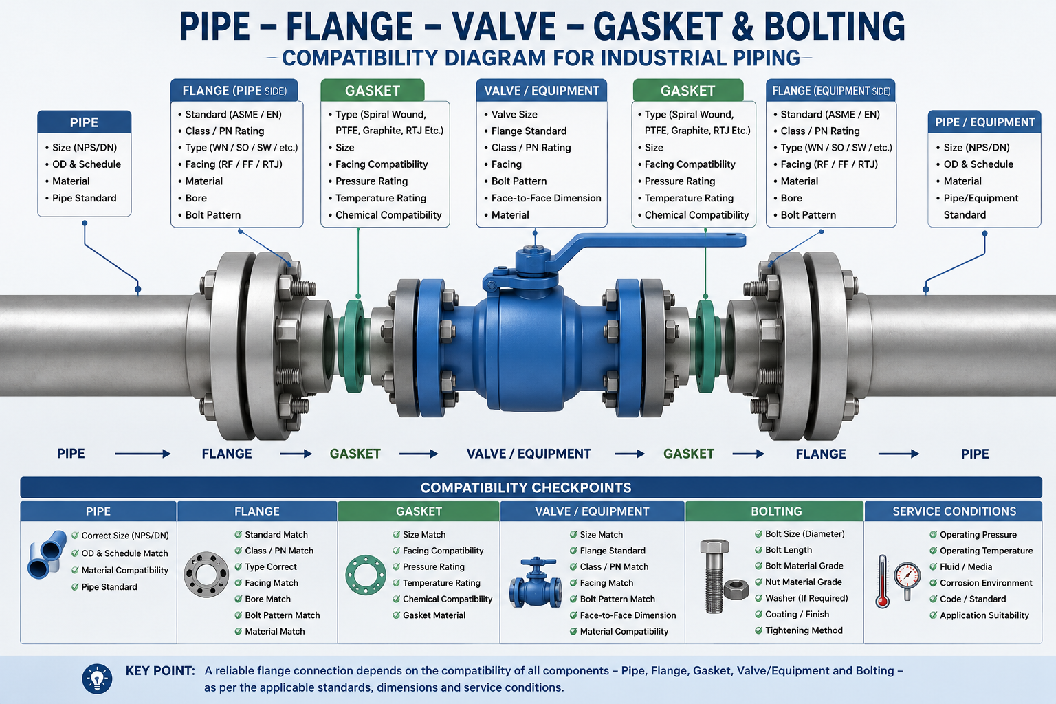
A practical way to look at a flanged joint is:
Pipe → Flange → Gasket → Valve / Equipment → Gasket → Flange → Pipe
Every interface in this assembly has to work together.
This flange compatibility guide explains how to check pipe flange compatibility, match flanges with valves and equipment, select compatible gaskets and bolting, and verify ASME and EN flange standards before ordering.
Flange Compatibility Checklist
Before ordering or connecting an industrial flange, verify:
- Pipe size: NPS or DN
- Pipe OD and schedule: especially for weld neck and socket weld connections
- Flange standard: ASME B16.5, ASME B16.47, EN 1092-1 or applicable project standard
- Pressure rating: ASME Class or EN PN
- Flange type: weld neck, slip-on, socket weld, threaded, lap joint or blind
- Facing: RF, FF or RTJ
- Material: carbon steel, stainless steel, alloy steel, duplex or other specified material
- Bore: compatible with the pipe and mating component
- Bolt pattern: number, diameter and bolt-hole circle
- Gasket: compatible with facing, pressure, temperature and process fluid
- Bolting: correct diameter, length, material grade and nut compatibility
- Mating component: pipe, valve, pump, vessel, heat exchanger or other equipment
In simple terms: flange compatibility is not determined by size alone. The standard, pressure rating, facing, dimensions, material and mating components must all be checked together.
What Makes Two Flanges Compatible? Key Compatibility Factors
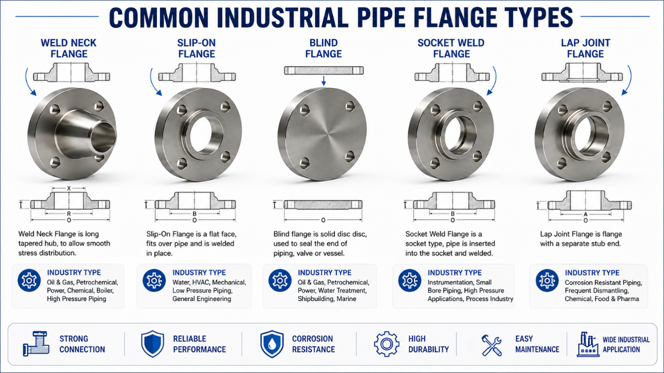
Two flanges are not necessarily compatible simply because they have the same nominal pipe size.
A proper flange compatibility check considers several dimensions and service conditions:
- Nominal size or DN/NPS
- Flange standard
- Pressure rating
- Flange type
- Facing
- Outside diameter
- Bolt-hole circle
- Number and diameter of bolt holes
- Bore
- Material
- Gasket arrangement
- Mating component
- Operating pressure and temperature
For example, a 6-inch Class 300 RF flange describes considerably more than the number “6.” The flange must be manufactured to the applicable dimensional standard, have the correct Class 300 dimensions, use the specified raised-face configuration, and match the component on the opposite side of the joint.
This is why a complete flange specification is much safer than an order description such as:
6” flange, Class 300.
Flange Compatibility Checklist by Component
| Component | What to Check |
|---|---|
| Pipe | NPS/DN, OD, schedule, material and standard |
| Flange | Standard, size, Class/PN, type, facing, bore and material |
| Valve | Size, pressure class, flange standard, facing, bolt pattern and face-to-face |
| Gasket | Size, facing, pressure, temperature and chemical compatibility |
| Bolting | Diameter, length, grade, thread and nut compatibility |
| Pump/Equipment | Nozzle size, standard, rating, facing, bore and bolt pattern |
| Installation | Bolt tightening, gasket compression and alignment |
1. Start With the Pipe: Size, Schedule and Bore
The first step in flange selection is establishing exactly what pipe the flange will connect to.
Nominal Size Is Only the Starting Point
NPS and DN identify the nominal size, but they do not completely define the pipe.
For example, two pipes may both be:
NPS 6
while having different wall thicknesses because of their schedules.
That difference becomes important when selecting a flange, particularly a weld neck flange, where the bore and welding-end configuration need to correspond with the pipe.
Important pipe information includes:
- NPS or DN
- Outside diameter
- Wall thickness
- Pipe schedule
- Pipe material
- Manufacturing standard
Why the bore matters
The bore of the flange should be considered together with the pipe dimensions and welding arrangement.
An incorrect bore can create:
- Installation difficulties
- Internal steps at the pipe-to-flange transition
- Welding problems
- Unwanted flow disturbances
- Inspection or fabrication issues
For this reason, a flange specification for a welded piping system should ideally identify the pipe size and schedule, not just the nominal diameter.
Practical example
Consider:
6” ASTM A106 Gr. B, Sch 40 pipe
versus:
6” ASTM A106 Gr. B, Sch 80 pipe
Both are 6-inch pipe, but their wall thicknesses differ. The flange selection should therefore be checked against the actual pipe dimensions and project specification.
2. Match the Flange Standard and Pressure Rating
The flange standard controls the dimensional relationship between the flange and its mating component.
Common standards encountered in international industrial projects include:
- ASME B16.5
- ASME B16.47
- EN 1092-1
- DIN-based flange specifications
- JIS flange standards
The applicable standard should be established before selecting the flange.
ASME Class and EN PN Are Different Systems
One of the most common specification mistakes is treating ASME Class and PN ratings as direct equivalents.
Examples include:
- ASME Class 150
- ASME Class 300
- ASME Class 600
- EN PN10
- EN PN16
- EN PN25
- EN PN40
These designations belong to different standards and dimensional systems.
Class 150 should not simply be replaced by PN16 because the numbers appear similar.
Pressure capability also depends on factors such as:
- Material
- Temperature
- Applicable standard
- Design conditions
- Piping code
The project specification should therefore determine the required flange standard and rating.
3. Select the Flange Type for the Connection
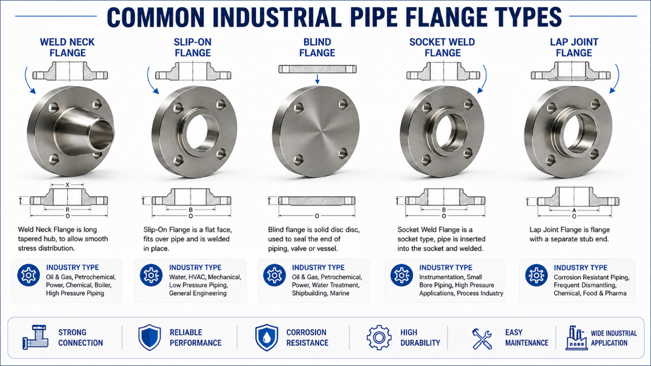
Flange type should be selected according to the piping design, fabrication method, pressure and temperature, accessibility, maintenance requirements and project specification.
Weld Neck Flanges
Weld neck flanges are widely used in demanding industrial piping because their hub and tapered transition provide a robust connection between the pipe and flange.
They are frequently specified in:
- Oil & gas
- Refineries
- Petrochemical plants
- Power generation
- Chemical processing
- High-pressure piping
Particular attention should be given to the bore, pipe schedule, material, pressure class and welding requirements.
Slip-On Flanges
Slip-on flanges fit over the outside of the pipe and are welded in position.
They are commonly found in general industrial and utility piping where the design permits their use.
Typical considerations include:
- Pipe outside diameter
- Wall thickness
- Welding arrangement
- Pressure and temperature
- Material
- Project piping class
A slip-on flange should not be selected merely because it is less expensive or easier to install. The flange type must be suitable for the actual service.
Socket Weld Flanges
Socket weld flanges are commonly used on smaller-diameter piping.
The pipe enters the socket in the flange and is welded according to the specified fabrication procedure.
Typical applications include:
- Small-bore process piping
- High-pressure utility lines
- Instrumentation-related piping
- Chemical and process systems
The pipe dimensions and socket dimensions need to be compatible.
Threaded Flanges
Threaded flanges provide a connection without welding.
They may be useful in applications where welding is undesirable or impractical, subject to the engineering specification.
The flange thread must match the pipe thread in:
- Thread standard
- Nominal size
- Thread form
- Compatibility
Threaded flange selection therefore requires more than matching the nominal pipe diameter.
Lap Joint Flanges
Lap joint flanges are used together with a stub end.
The flange can rotate around the stub end, which can simplify alignment during assembly and make repeated dismantling more convenient.
They are particularly useful where:
- Frequent disassembly is required
- Alignment is important
- Corrosion-resistant piping materials are expensive
- A separate stub end is part of the piping design
The flange and stub end should be considered as a complete assembly.
Blind Flanges
Blind flanges are used to close a pipe, nozzle or branch connection.
Typical applications include:
- Pipeline termination
- Equipment isolation
- Maintenance
- Pressure testing
- Future connection points
The required thickness, facing, material and pressure rating should be determined from the applicable standard and design conditions.
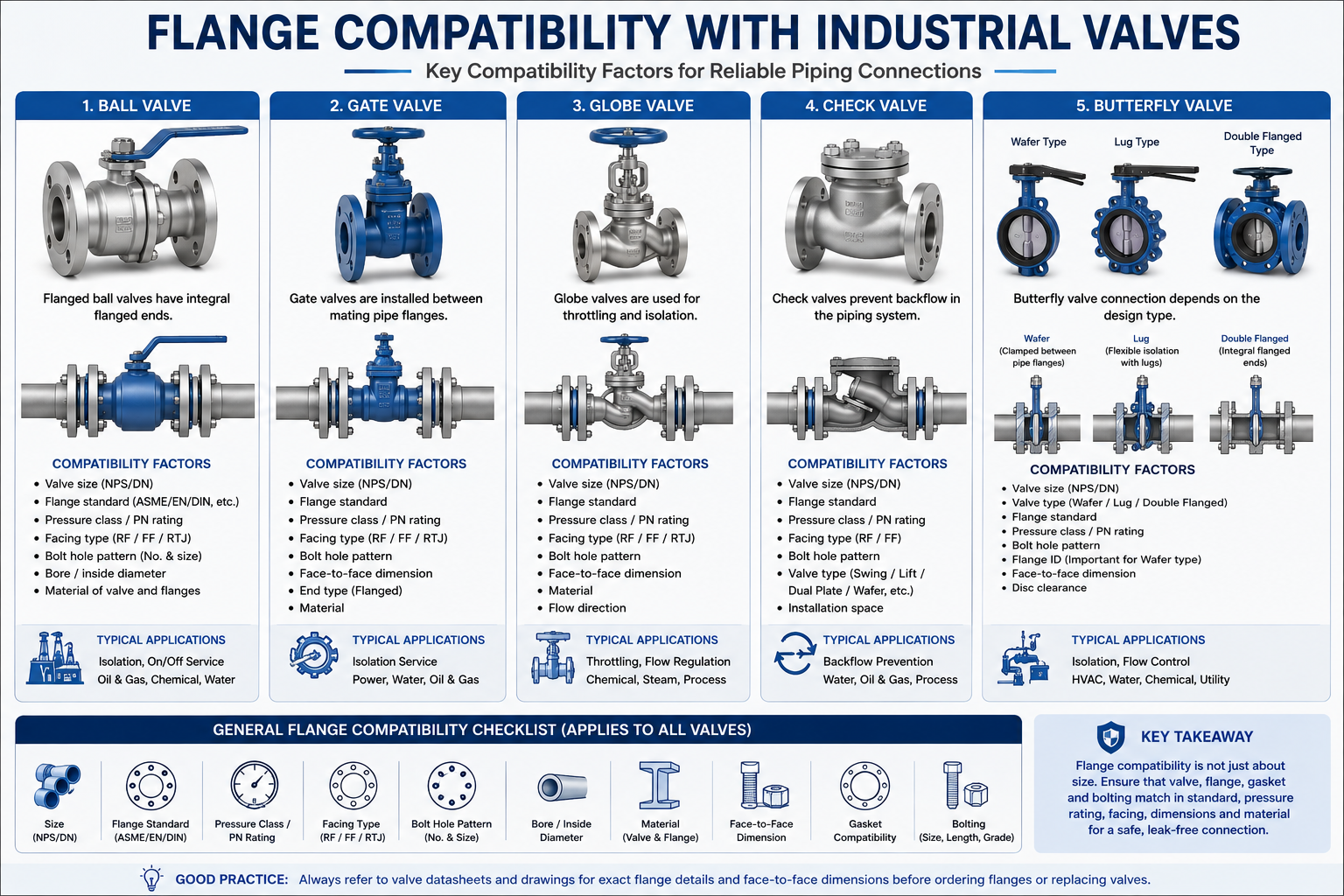
4. How to Match Flanges With Industrial Valves
Valve connections deserve particular attention because the flange is often being selected to connect a piping system to a valve rather than directly to another pipe.
The key parameters are:
Valve size → flange standard → pressure class → facing → bolt pattern → mating flange
The valve’s dimensional drawing or datasheet should be used whenever available.
Ball Valve Flange Compatibility
A flanged ball valve normally has integral flanged ends.
For example:
6” Class 300 RF ball valve
requires mating pipe flanges compatible with the valve’s:
- Nominal size
- Applicable flange standard
- Class
- Facing
- Bolt-hole pattern
- Dimensions
A flange should therefore be selected from the valve and piping specifications together, rather than simply ordering a flange of the same nominal size.
For critical or replacement applications, the valve manufacturer’s dimensional drawing should be checked.
Gate Valve Flange Compatibility
Flanged gate valves are commonly installed between mating pipe flanges.
Important parameters include:
- Valve flange standard
- Pressure class
- Facing
- Bolt-hole arrangement
- Valve face-to-face dimension
- Pipe flange dimensions
For replacement work, the face-to-face dimension can be particularly important. A valve may have the correct flange connection and still be unsuitable as a direct replacement if its overall installation length differs.
Globe Valve Flange Compatibility
Globe valves are also available with flanged ends and are commonly used for throttling and isolation services.
The flange connection should be checked in the same way as other flanged valves:
- Size
- Standard
- Class
- Facing
- Bolt pattern
- Face-to-face dimension
Because globe valves can have different body configurations, the dimensional drawing should be referenced where installation space is restricted.
Check Valve Flange Compatibility
Flanged check valves may be supplied in several body designs, including:
- Swing check
- Piston lift check
- Dual-plate check
- Wafer check
- Other specialized configurations
The valve connection must be checked against the piping flange arrangement.
For wafer-style check valves, the available installation space and flange inside diameter can also affect compatibility.
Butterfly Valve Flange Compatibility
Butterfly valves require special attention because wafer, lug and double-flanged designs do not have the same installation arrangement.
Wafer butterfly valve
A wafer butterfly valve is installed between two pipe flanges.
The valve body is clamped between the flanges, so the piping flanges determine the bolting arrangement around the valve.
The following should be verified:
- Valve size
- Valve pressure rating
- Flange standard
- Bolt-hole arrangement
- Flange inside diameter
- Disc clearance
- Face-to-face dimension
Lug butterfly valve
Lug-type valves have lugs around the body and can be installed between flanges.
Depending on the design, they can provide useful flexibility for maintenance and isolation arrangements.
Double-flanged butterfly valve
This design has integral flanged ends and connects directly to mating pipe flanges.
The dimensional relationship is therefore closer to that of other conventional flanged valves.
Valve and Flange Compatibility Checklist
| Valve Type | Key Compatibility Checks |
|---|---|
| Ball Valve | Size, Class/PN, flange standard, facing, bolt pattern |
| Gate Valve | Flange standard, Class/PN, facing, bolt pattern, face-to-face |
| Globe Valve | Size, rating, facing, bolt pattern, face-to-face |
| Check Valve | Valve configuration, flange dimensions, bolt pattern, installation space |
| Butterfly Valve | Wafer/lug/flanged type, flange ID, bolt pattern, disc clearance |
| Forged Gate Valve | Flanged, socket weld or threaded connection configuration |
5. Flange Facing and Gasket Compatibility
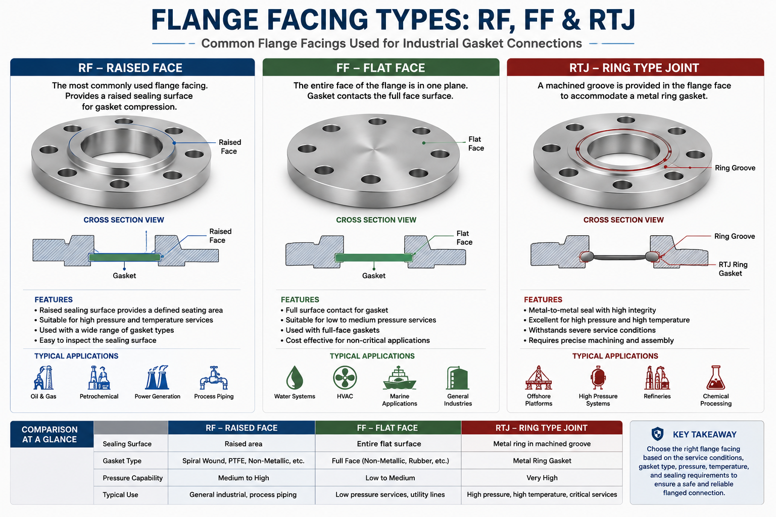
The flange face is directly related to the gasket and sealing arrangement.
Common configurations include:
- Raised Face (RF)
- Flat Face (FF)
- Ring Type Joint (RTJ)
The gasket must be suitable for the selected facing.
Raised Face — RF
RF is widely used in industrial process piping.
The raised sealing area provides a defined gasket seating surface.
Flat Face — FF
Flat-face connections use a larger gasket seating area and require appropriate gasket selection and mating-face arrangement.
Flat-face connections are commonly encountered in certain lower-pressure or equipment applications, depending on the piping specification.
Ring Type Joint — RTJ
RTJ flanges have a machined ring groove designed to receive a metallic ring gasket.
The gasket, flange groove and mating flange must be designed as a complete system.
An RTJ flange should not be treated as interchangeable with an RF flange simply because the nominal size and pressure class are the same.
6. How to Select the Right Gasket for a Flanged Joint
Gasket selection depends on both the flange configuration and the service conditions.
Important factors include:
- Flange size
- Flange facing
- Pressure
- Temperature
- Process fluid
- Chemical compatibility
- Flange surface condition
- Required sealing performance
- Applicable standard or project specification
Common gasket constructions include:
- Spiral wound
- PTFE
- Graphite
- Non-metallic sheet
- Kammprofile
- RTJ metallic rings
Example
A gasket material suitable for a water line at moderate temperature should not automatically be selected for a high-temperature hydrocarbon process.
Likewise, an RTJ connection requires the correct metallic ring gasket and matching flange groove.
The gasket should therefore be specified as part of the complete flange joint rather than treated as a generic accessory.
7. Flange Bolting: Size, Length, Grade and Tightening
Bolting provides the clamping force that keeps the gasket compressed between the mating flange faces.
For a typical industrial flange connection, the specification may involve:
- Stud bolts
- Hex nuts
- Washers where specified
- Special bolting grades for particular services
Important parameters include:
- Number of bolts
- Bolt/stud diameter
- Thread specification
- Bolt/stud length
- Material grade
- Nut grade
- Coating or surface treatment where specified
How is bolt length determined?
Bolt length depends on the complete joint stack-up:
Flange thickness + gasket thickness + mating flange thickness + washer thickness, if applicable + required nut engagement
This is why bolt length cannot be reliably determined from flange nominal size alone.
8. Bolt Tightening and Gasket Compression
Correct components can still produce an unreliable flange joint if the assembly procedure is poor.
The objective of tightening is to achieve appropriate and reasonably uniform gasket compression without overstressing the flange, gasket or fasteners.
Depending on the application, project procedures may specify:
- Cross-pattern tightening
- Multiple tightening passes
- Controlled torque
- Hydraulic tensioning
- Final torque verification
Uneven tightening can cause:
- Uneven gasket compression
- Flange distortion
- Local leakage
- Fastener overstress
- Gasket damage
For critical services, the installation procedure should be treated as part of the overall flange joint design.
9. Material Compatibility in Flanged Connections
Flange material should be selected according to the complete operating environment.
Common materials include:
Carbon Steel
Examples include:
- ASTM A105 / A105N
- ASTM A350 LF2
- ASTM A694 grades for specified applications
Stainless Steel
Common grades include:
- ASTM A182 F304/F304L
- ASTM A182 F316/F316L
Alloy Steel
Examples include:
- ASTM A182 F11
- ASTM A182 F22
Duplex and Super Duplex
These materials are frequently selected where corrosion resistance and mechanical performance are important, including certain seawater, offshore and chemical applications.
Material selection should consider:
Pressure + temperature + process fluid + corrosion environment + design code + project specification
A more corrosion-resistant material is not automatically the correct material if it does not meet the complete engineering specification.
10. Flange Compatibility With Pumps, Vessels and Other Equipment
Piping flanges are frequently connected to equipment nozzles rather than another pipe.
Examples include:
- Centrifugal pumps
- Pressure vessels
- Heat exchangers
- Tanks
- Filters
- Strainers
- Skid packages
The equipment nozzle may have its own specified:
- Flange standard
- Size
- Pressure rating
- Facing
- Bore
- Material
- Bolt pattern
Do not assume the equipment nozzle follows the piping flange specification
For packaged equipment, the nozzle drawing or equipment datasheet should be checked before the connecting flange is ordered.
This is particularly important where the equipment manufacturer has specified a particular flange facing or dimensional arrangement.
11. Why Valve Face-to-Face Dimensions Matter
Flange compatibility is not limited to the bolt holes.
A valve can have the correct:
- Size
- Class
- Flange standard
- Facing
- Bolt pattern
and still create an installation problem because its face-to-face dimension differs from the existing valve.
This is particularly important for:
- Replacement valves
- Brownfield projects
- Plant maintenance
- Existing skid installations
- Piping systems with limited flexibility
Example
An existing gate valve may have a specific face-to-face dimension established by the original piping design.
If a replacement valve is longer, the pipe may need to be cut or modified.
If it is shorter, additional piping or modification may be required.
For replacement applications, always compare the valve’s dimensional drawing with the existing installation.
12. Common Flange Compatibility Mistakes
1. Specifying only the flange size
“6-inch flange” leaves too many variables undefined.
2. Treating Class 150 and PN16 as interchangeable
The designation systems and dimensions are different.
3. Ignoring pipe schedule
The pipe wall thickness can affect the required flange bore and welding configuration.
4. Mixing dimensional standards
ASME, EN, DIN and JIS flange dimensions should not be assumed interchangeable.
5. Selecting the gasket without checking the facing
RF, FF and RTJ require different sealing arrangements.
6. Checking only the valve’s nominal size
The flange standard, class, facing and bolt pattern also have to match.
7. Treating wafer and flanged butterfly valves as the same connection
Their installation arrangements are different.
8. Ordering bolt lengths without considering the joint
The complete stack-up determines the required length.
9. Replacing a valve without checking face-to-face dimensions
A flange-compatible valve may still not fit the existing pipeline.
10. Selecting materials independently
The flange, bolting and gasket should be evaluated against the process conditions and project specification.
What Should an Industrial Flange RFQ Include?
A clear flange RFQ reduces assumptions and makes technical comparison between suppliers much easier.
A practical specification could look like this:
Flange Type: Weld Neck
Size: NPS 6
Standard: ASME B16.5
Class: 300
Facing: RF
Material: ASTM A105N
Bore: Suitable for specified pipe schedule
Quantity: 20 pcs
Application: Process piping
Documentation: EN 10204 3.1 MTC
If the flange will connect to a valve or equipment nozzle, include the relevant valve datasheet, equipment drawing or flange dimensional details.
This is particularly useful for replacement work and non-standard project requirements.
Flange Compatibility: A Simple Engineering Approach
A reliable way to approach flange selection is to work through the connection in this order:
1. Identify the pipe
Size → OD → Schedule → Material
↓
2. Identify the piping standard
ASME / EN / DIN / JIS / Project specification
↓
3. Establish the pressure and temperature
Class / PN → Design pressure → Design temperature
↓
4. Select the flange
Type → Facing → Material → Bore
↓
5. Identify the mating component
Pipe / Valve / Pump / Vessel / Equipment
↓
6. Select the gasket
Facing → Service → Pressure → Temperature → Material
↓
7. Select the bolting
Diameter → Length → Grade → Nut → Tightening method
This approach helps prevent the common situation where every individual component appears correct but the assembled joint is not.
15. Flange Compatibility Checklist Before Ordering
Before placing an industrial flange order, confirm the following.
Pipe
- NPS/DN
- Outside diameter
- Schedule
- Material
- Applicable pipe standard
Flange
- Type
- Standard
- Class/PN
- Facing
- Bore
- Material
- Quantity
Valve or Equipment
- Connection type
- Flange dimensions
- Bolt-hole pattern
- Face-to-face dimension
- Equipment nozzle dimensions where applicable
Gasket
- Type
- Facing
- Material
- Pressure
- Temperature
- Process compatibility
Bolting
- Diameter
- Length
- Material grade
- Nut grade
- Tightening requirements
A complete specification makes it easier for manufacturers and procurement teams to identify the correct product and reduces the risk of incompatibility during installation.
16. Flange Compatibility for EPC and Industrial Projects
For EPC contractors and industrial procurement teams, flange selection is often part of a larger piping package.
A project may require flanges to connect:
- Process piping
- Gate valves
- Ball valves
- Globe valves
- Check valves
- Butterfly valves
- Pumps
- Heat exchangers
- Pressure vessels
- Storage tanks
- Skid-mounted equipment
In such projects, compatibility should be checked against the approved piping class, equipment datasheets, valve datasheets, project standards and applicable international specifications.
Procurement teams should also consider:
- Material Test Certificates
- Dimensional inspection
- Product traceability
- Third-party inspection
- Pressure or other applicable testing
- Marking
- Export packing
- Project documentation
Working with an experienced industrial flange manufacturer and supplier can simplify procurement when multiple flange configurations, materials and documentation requirements are involved.
Flange selection is often treated as a simple piping-material decision, but the actual connection is a complete mechanical assembly.
The flange must work with the pipe.
The flange facing must work with the gasket.
The valve or equipment flange must match the piping connection.
The bolts must provide the required clamping force.
And all of these components must be suitable for the pressure, temperature and service environment.
A useful specification therefore goes beyond:
“6-inch Class 300 flange.”
A complete requirement defines the size, standard, rating, flange type, facing, material, bore and mating connection, followed by the appropriate gasket and bolting specifications.
For industrial projects, taking a few additional minutes to verify these interfaces before ordering can prevent much more expensive problems during fabrication, installation and commissioning.
C-Way Engineering Exports supplies industrial flanges in multiple configurations, materials, sizes and pressure ratings for oil & gas, petrochemical, chemical, water, marine, power and other industrial applications.
Flange requirements can be manufactured and supplied according to the applicable dimensional standard, material specification and project requirements.
Need Help Checking Flange Compatibility?
Selecting the correct flange requires more than matching nominal pipe size. Flange standard, pressure class, facing, bore, material, gasket, bolting and mating equipment should all be verified before procurement.
For a technical review or quotation, share:
- Pipe size and schedule
- Flange standard
- Pressure Class or PN rating
- Flange type
- Facing
- Material
- Mating valve or equipment
- Required quantity
- Inspection and documentation requirements